Routers
Secure work from home (L2TP)
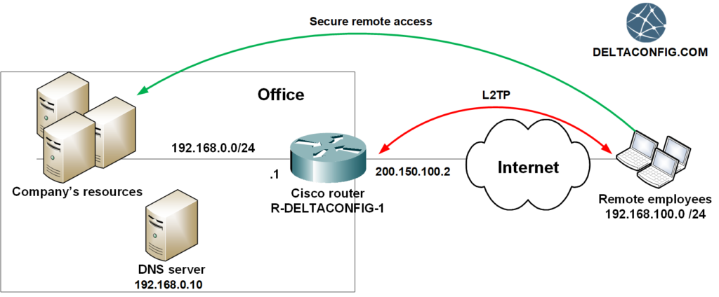
The situation occurred due to the coronavirus pandemic demonstrated the importance of having remote access for employees to the company resources. Which of course, has to be easy, convenient and secure.
Recently remote access technology was a privilege mainly for top managers and administrators. Now, it is a vital need even for an ordinary employee.
The technology itself and different ways of remote connections already exist for a long time. However, due to its weak spread, most managers don't understand which equipment is needed and how such access can be set up. And most importantly - how much does it cost?
What do we offer
For those companies and managers, who value their time and resources, my colleagues and I offer a turnkey solution for establishing remote access VPN based on the Cisco Systems equipment.
Solution includes:
Analysis of the existing company network infrastructure
Plan and design of the individual solution
Help with the choice of the equipment models and their purchase
Equipment set-up and configuration
Support of the whole solution after implementation
Preparation of the detailed documentation, which includes the description of the system and the network diagram.
Note that sometimes the purchase of additional equipment is not necessary at all. Perhaps, remote access VPN can be set up even on the existing network equipment.
As a basis, we always suggest Cisco Systems equipment. However, the cases, when companies got similar products of other manufacturers aren't rare. We will help to organize secure remote access of employees on it, as well, if it's possible.
Types of remote access technology
Two most popular technologies for organizing remote access VPN are connection by L2TP protocol and via the Cisco Anyconnect application. These solutions are time-tested and have already proven their effectiveness, simplicity of set-up and ease of the support.
L2TP
To connect, the employee uses the standard client, which is available on every operating system, whether it's Windows or MAC. No additional installation on the workstation is required. You only need to enter the company router's address, login and password. No additional licenses required.
Anyconnect
Particular client for VPN using SSL protocol by Cisco Systems. When connecting for the first time, installation on the workstation is required. The client is easy and convenient at work. Creating a secure connection is reduced to the simple pressing of a "Connect" button. Additional hardware licenses may be required.
The options of connection aren't limited with these two ways so far. If necessary, we can offer you another ones as well.
How much does it cost
The final price consists of the following components:
The equipment price
The price of the configuration services
The price of the support
As discussed above, buying the brand-new equipment may be not necessarily at all, and what for the support of the solution - company's own IT specialists may be able to conduct it. Concerning the price of the setting, it will be approximately twice cheaper, than if your company decided to hire the specialists with the required knowledge, experience and qualification. In this case, there are no problems with staff search, additional tax deductions, employees' day-offs, bonuses, and other issues.
Trying to spend less
For sure it is possible to organize the employee's access to company resources in more straightforward ways. For example, recently, one company's staff opened access for the employees from the outside to a terminal server via Remote Desktop (RDP). The very next day, as a result of using one of the server's vulnerabilities, attackers hit absolutely all workstations and almost all servers. Malware software ("virus") encrypted all data on the hard drives, which completely stopped the company work for a couple of days.
But how much does at least an hour of company downtime cost? Such security savings are costly for any kind of business.
How to reduce the costs
Price of one Cisco router with all the required licences can exceed 5k-10k USD (the price of models for small and medium-sized companies). However, such costs are affordable not for everyone. One of the ways for reducing the expenses – is to get used equipment. These are the devices which were used in banks and other large companies and which eventually are decommissioned, replaced with modern models and sold on the market.
The price of such devices of comparable performance is several times lower and ranges from 500$ to 2000$ for similar models.
For sure the risk of failure of such equipment is higher than of the brand-new one but still minimal, especially if there is a guarantee from the seller. Besides, such a difference in price allows you to potentially purchase two devices and configure them in fault-tolerant mode.
Additional benefits
In addition to creating a system for secure remote access for employees, you will receive an external audit of your network, which in any case is carried out while studying the company's network infrastructure.
Also, after the implementation of the remote access system, along with its support we can support the entire network of the company. Read more about this service on the "Cisco Outsourcing" page.
Contacts
To get started, contact us via Skype, Whatsapp or Telegram. Tell us about your needs, and we will surely find a common language and an occasion for long and mutually beneficial cooperation.
Skype – nevidimkastd
Email — smogdelta@gmail.com
Whatsapp Telegram — +7-916-461-18-36
IP SLA on Cisco Router
Sooner or later, but every company faces the problem with the Internet connection being out of order. And right after that, the question about backup channel arises. What settings needed to be done to automatically switch to backup link in case of an accident?
This article describes the configurations for Cisco 881 routers and similar models (1841, 1941, 2900, 3800...). If you have Cisco ASA, the settings for it are described in the article Dual WAN on Cisco ASA.
One of the easiest and most effective ways to configure a Cisco router - is using the IP SLA monitor. The device will track the availability of the primary Internet provider, and once the connection is lost (certain address won't respond to ICMP requests during several seconds), it will forward traffic through the backup link.
Let’s take a look at the settings, considering the example of a standard router model for small office - Cisco 881.
Fa 4 interface - the primary service provider is connected here. This is an l3 interface of OSI model, so the ip address is assigned directly to the interface;
FastEthernet 3 (Vlan 3) - the backup ISP is connected.
Fa 0 interface (Vlan 1) - the local office network (LAN) is connected here;
If you have another model of a router, then, the difference will be only in the name of the interfaces, but not in the settings itself.
Goal: to set the resilient Internet connection (dual wan).
Step 1. Routes check.
Checking current routes on the device. For convenience we are using sh run | inc route command that allows seeing current configuration, containing the word «route»
R-DELTACONFIG-1# sh run |
Ip route 0.0.0.0 0.0.0.0 10.10.10.1 1
Translating from the device's language to a more understandable, "human" one, it will sound like this:
«Forward all packages, about which I know to the outside interface through the gateway 10.10.10.1».
Router “knows” only about networks, which are connected to it directly or for which the routes strings are set up.
Step 2. The backup provider settings.
On the router, the outside interface Fastethernet 4 is already set up. Here the primary ISP is connected. So In current configuration (can be shown using command sh run) there will be strings similar to these:
R-DELTACONFIG-1# sh run
…
interface
ip address 255.255.255.252
Now, let's add the settings for the backup link, that is connected with Fa 3/ Vlan 3.
Firstly, we need to create Vlan to connect the backup service, bind it to one of its free ports, and after that set an IP-address.
Creation of Vlan 3
R-DELTACONFIG-1
vlan database
R-DELTACONFIG-1
name BACKUP_ISP
To check current settings, you can use command sh current, without leaving the VLAN configuration mode. It’s enough to have Vlan 3 in the list of existing interfaces.
R-DELTACONFIG-1 (vlan)#
To bind Vlan 3 to FastEthernet 3 interface, you must leave the Vlan set up mode and then enter the regular conf t configuration mode. After that, bind Vlan 3 to the FastEthernet 3 interface and activate it with the command no shut.
R-DELTACONFIG-1
exit
conf t
R-DELTACONFIG-1
interface
no shut
And right after that set an IP address and activate the interface using the command no shut.
R-DELTACONFIG-1 (config)#
interface
ip address 255.255.255.252
no shut
If all the wires are connected and the settings are correct, then the gateway of the backup provider should be available from the Cisco 881 router.
R-DELTACONFIG-1 #
Type escape sequence to abort.
Sending 5, 100-byte ICMP Echos to 20.20.20.1, timeout is 2 seconds:
!!!!!
, round-trip min/avg/max = 1/2/4 ms
Step 3. Configuration of the ISP availability tracking.
In order to make Cisco 881 router track the availability of the primary link, it is necessary to configure the IP SLA monitor feature. In equal time intervals, the ping (ICMP request) will be sent on the 1 provider's gateway address (the main one). The receival of the responsive package (ICMP response) means the availability of the channel.
What to check?
In most cases, both the address of the external interface and an ISP gateway are known beforehand. So, that's why it is enough to check only the availability of the provider gateway address. But here's a trick. What will happen if the gateway is still available, but the fault has turned out being somewhere in the provider network? I.e. "the Internet isn't working", though the gateway is accessible. Actually - nothing. The router would not recognize the fault, and it won't switch to the backup mode. Another similar case is when an ISP provides a dynamic address, for example, using PPPoE technology.
To avoid such a case, usually, the stable working address on the Internet is being chosen, which can be located in any place in the world. Then, on the Cisco 881 router, the static route to the chosen address through the gateway of main ISP is being set. And the availability of the default gateway to the side of the main provider is being placed depending on the availability of the chosen address. Then, whatever happens with the connection, whether it is with the router settings problem, connection operator disruption or other reason, the switch to the backup ISP will be performed automatically. At the same time, the disadvantage of such approach is that the needed address always will be unavailable along with the primary provider. For such aims, I recommend using the address 1.1.1.1, which is stably available but is used quite rarely in daily users’ or devices work.
It is written kind of complicated, isn’t it? Let’s simplify it for the algorithm of the 881 router’s actions:
Router, keep in mind, that the host 1.1.1.1 is always located behind the main ISP gateway 10.10.10.1
Router, check the availability of the host 1.1.1.1 ones in 10 seconds.
If host 1.1.1.1 is available, then the default gateway - address of the 1st ISP
If host 1.1.1.1 is not available, then the default gateway - address of the 2nd ISP
Now, we are setting the static route through the main provider to the address 1.1.1.1
R-DELTACONFIG-1 (config)#
ip route 255.255.255.255
Activating the IP SLA function
R-DELTACONFIG-1 (config)#
ip sla 1
icmp-echo source-interface
threshold 10000
ip sla schedule 1 life forever start-time now
track 1 ip sla 1 reachability
For reference:
threshold 10000 - The requests will be sent 1 time in 10 seconds.
Step 4. Checking the work of the tracking tool.
For checking the tracking work of the IP SLA the command sh ip sla statistics is used.
R-DELTACONFIG-1#
IPSLAs Latest Operation Statistics
IPSLA operation id: 1
Latest RTT: 4 milliseconds
Latest operation start time: 14:07:40 MSK Thu Aug 8 2019
Latest operation return code: Over threshold
Number of failures: 0
Operation time to live: Forever
Number of successes: 15 – shows the number of successful ICMP requests
Number of failures: 0 – shows the number of failed requests
Before executing any of the following steps check the output of this command several times, to make sure that the counter of the successes grows over time. That means that the main channel is working stably and can continue the configuration without the risk of losing the connection with the Internet.
Step 5. The default gateway for the backup provider.
For backup provider, the default gateway is required to be specified, where the Cisco 881 router will send all the packages, but with one difference - this route shouldn’t be considered when the primary provider is available. To enable this, lower the route priority, that is also called as ‘administrative distance’. In other words, it has to be longer.
By default, the value of the administrative distance for a static route - 1.
Let’s set for the backup channel the value, that is close to maximum - 250 (very expensive)
R-DELTACONFIG-1 (config)#
ip route 0.0.0.0 0.0.0.0 20.20.20.1
After such update, in the Cisco 881 router configuration has to be 2 default routes.
R-DELTACONFIG-1# sh run | inc route
ip route 255.255.255.255
ip route 0.0.0.0 0.0.0.0 10.10.10.1
ip route 0.0.0.0 0.0.0.0 20.20.20.1
Step 6. The switch activation.
The final step is to bind the main route to the tracking function by the channel availability (IP SLA). Firstly, we have to add the new string for the default gateway marked as ‘track 1’ and remove the old one.
R-DELTACONFIG-1 (config)#
ip route 0.0.0.0 0.0.0.0 10.10.10.1 1
After that, in the final Configuration, there will be two strings for the default gateways.
R-DELTACONFIG-1# sh run | inc route
ip route 255.255.255.255 10.10.10.1
ip route 0.0.0.0 0.0.0.0 10.10.10.1
ip route 0.0.0.0 0.0.0.0 20.20.20.1
If the route strings exist for some networks, besides the default gateway, then you should take into account their presence during configuration, thinking through the switching logic similarly to the default gateway.
Step 7. The NAT adjustment.
The most important thing, that distinguishes the dual wan configuration on Cisco 881 and Cisco ASA routers - is the necessity to reconfigure the translation rules of the NAT (conversion of the internal private addresses into public ones of the external interface). If for Cisco ASA it is enough to duplicate the NAT settings for the backup provider, then for Cisco routers it is necessary to reconfigure the command logic.
The ‘Regular’ NAT settings to access the Internet, for users, boil down to selecting the range of the internal addresses and adding the rule “translate ‘these addresses’ into the external interface address”. In fact, it is just the description of the traffic, BEFORE it gets into the internal router interface.
ip access-list standard
permit 192.168.10.0 0.0.0.255
Interface Vlan 1
ip nat inside
Interface Fa 4
ip nat outside
ip nat inside source list interface
In case of the realization of a resilient switching to the backup ISP using the IP SLA feature, it is necessary to use the route-map. It is the extended function of the traffic control flow, in which the condition (which traffic) and action (what to do with it) is specified. In our case, for each of the providers, a route-map is created only with "conditions", which are:
Pre-created list of ACL_NAT access, in which the traffic is reflected for all internal hosts
Output interface (own for each of the providers)
route-map permit 10
match ip address
match interface
route-map permit 10
match IP address
match interface
Then, you need to add rules for NAT, which refer to the route-map.
ip nat inside source route-map interface overload
Don't forget to check, that on each of the three interfaces, through which the traffic is passed, there are strings about belonging to the NAT.
Interface Vlan 1
ip nat inside
Interface Fa 4
ip nat
interface Vlan 3
ip nat
This article was written by Alexey Yurchenko
Back to Table of contents
ip nat outside on cisco router
Overlapping IP address ranges in your own LAN and the local area network of the organization you're partnering with is a common issue that network administrators are faced with in their daily jobs. The textbook solution for this issue is NAT.
Let us skip the explanations of how to do basic configurations for dynamic and static NAT scenarios that you use when you need to hide your internal IP address behind a public IP address in order to get access to outside resources (dynamic NAT), or allow internal resources to be available from the outside world (static NAT). You can find tutorials for these types of configurations in the "Basic Configuration of Cisco Router" and "Basic Configuration of Cisco ASA" articles, as well as the "Using NAT" article.
Destination address substitution
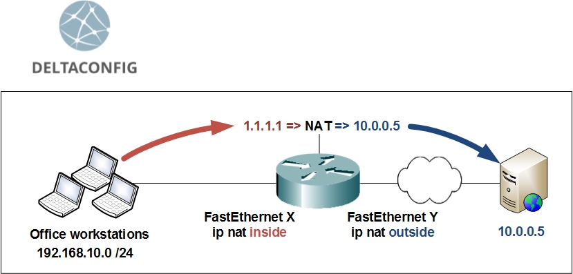
Let us look at an example, in which we need to create a special fictional dummy IP address, that is used to impersonate the real IP address that overlaps with something in your network, and redirects the traffic towards the real destination.
10.0.0.5 – the actual IP address of the server that you need to gain access to
1.1.1.1 – dummy IP address, that will redirect the user's traffic to 10.0.0.5
In order to implement this scenario, you need to configure the router's interfaces to be recognized as either inside or outside network using the following commands:
conf t
interface FastEthernet X
ip nat inside
$nbsp;
interface FastEthernet Y
ip nat outside
After you've done that, enter the command:
ip nat outside source static 10.0.0.5 1.1.1.1
Important!
After creating that NAT rule, you must add a static route for the dummy IP address, directing traffic towards the real server.
A) If the server is located on a network directly connected to one of the router's interfaces, then use the server's real IP address as the next hop:
ip route 1.1.1.1 255.255.255.255 10.0.0.5
B) If the server is located farther in the network behind some other router, use that devices IP address as the next hop (x.x.x.x):
ip route 1.1.1.1 255.255.255.255 x.x.x.x
Verifying NAT
Use the command sh ip nat translations in order to check the active translation rules for your IP addresses. Your output should look similar to this:
R-DELTACONFIG-1#sh ip nat translations
Pro Inside global Inside local Outside local Outside global
--- --- --- 1.1.1.1 10.0.0.5
--- --- --- 1.1.1.2 10.0.0.6
icmp 192.168.10.10:19662 192.168.10.10:19662 1.1.1.1:19662 10.0.0.5:19662
Substituting source and destination IP addresses at the same time
The scenario described above does not limit you from using "regular" NAT along with it. If you need to hide the real IP address of your workstation behind some "outside" IP, you will have to create the regular translation rules, like you use for dynamic NAT, for example.
Let's say the real IP address of our workstation is 192.168.10.5 (source IP), and it needs to be hidden behind a dummy IP address of 2.2.2.2
Add the configuration lines for dynamic source address translation:
ip access-list extended ACL_NAT
permit ip host 192.168.10.5 any
$nbsp;
ip nat pool NAT 2.2.2.2 2.2.2.2 netmask 255.255.255.0
$nbsp;
ip nat inside source list ACL_NAT pool NAT
As a result of this configuration, the original packet from source IP 192.168.10.5 of our workstation destined for 1.1.1.1 will be converted into a packet with source 2.2.2.2 and destination 10.0.0.5 as it traverses our router.
Important!
Don't forget to check the routes on all your network devices if you encounter problems with this configuration. All of your devices need to "know" not only the routes to your real IP addresses, but to the dummy ones, as well.
Important!
Don't forget to save your configuration changes on all your devices with the command write or copy run start. Otherwise you will lose all your changes after the next reload.
R-MAIN#write
Building configuration...
[OK]
This article was written by Alexey Yurchenko
Back to Table of contents
Using NAT on Cisco router
The hardest thing about NAT in Cisco routers and ASA firewalls is understanding how to use the technology in real life. Tons of guide papers have been written, the Internet is full of gigabytes of information on the topic, yet the subject remains relevant. Truth is, 95% of absolute majority of people will only need to use just one of the two types of connections.
1) PAT (Port Address Translation)
A bunch of internal IP addresses are translated into a single external IP address when connecting to the outside world. While each packet destined to outside networks is being processed by a router or a Cisco ASA, the correlation of the actual internal IP address and port number of the source of the TCP connection is being remembered, which allows to correctly perform the reverse translation and transfer return packets.
This kind of NAT is used when you need to allow access FROM an internal network to external resources (such as the Internet).
2) Static NAT
This is translating addresses one-to-one. A specific public IP address is put together with an internal IP address. This kind of NAT translation is used when you need access FROM the outside world to a server or resource within the internal network or a DMZ.
Summary:
If you need access from the internal LAN to the outside world, it is most likely that you will have to configure PAT.
If you need access from the outside world to a certain internal resource, then you will have to configure static NAT.
NAT configuration examples for the above cases
Cisco ASA (IOS below 8.3)
PAT
global (outside) 1 interface
nat (inside) 1 192.168.10.0 255.255.255.0
Static NAT
static (dmz,outside) interface 10.0.0.20 netmask 255.255.255.255
Important!
The keyword interface in this code specifies the devices own IP address that is assigned to the external interface (1.1.1.1). If the translation is being made into another IP address from the pool of IP addresses belonging to the external interface, then that address is specifically mentioned.
Cisco ASA (IOS above 8.3)
PAT
object-group network NET_LAN
network-object 192.168.10.0 255.255.255.0
nat (inside,outside) source dynamic NET_LAN interface
Static NAT
object network NAT_OUTSIDE_1.1.1.1
host 10.0.0.20
nat (dmz,outside) static interface
Cisco IOS Router
PAT
interface Ethernet X
ip address 192.168.10.1 255.255.255.0
ip nat inside
interface Ethernet Y
ip address 1.1.1.1 255.255.255.252
ip nat outside
ip nat pool POOL_PAT 1.1.1.1 1.1.1.1 //No mistakes here. An external address is mentioned twice.
ip access-list standard ACL_PAT
permit ip 192.168.10.0 0.0.0.255
ip nat inside source list ACL_PAT pool POOL_PAT overload
Static NAT
interface Ethernet Z
ip address 10.0.0.1 255.255.255.0
ip nat inside
interface Ethernet Y
ip address 1.1.1.1 255.255.255.252
ip nat outside
ip nat inside source static 10.0.0.20 interface Ethernet Y
Important!
This article includes only the simplest configuration examples for NAT translations, on purpose. More complex examples are covered in articles about basic Cisco router and Cisco ASA configurations.
Also there is a full explanation of port forwarding (static NAT) on Cisco ASA with configuration examples in this article.
This article was written by Alexey Yurchenko
Back to Table of contents
Routes and Routing Explained
How to add a route
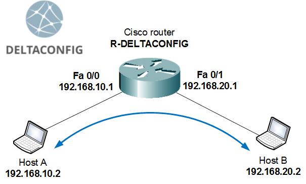
By default, any router or firewall is aware only of those networks and subnets that are directly connected to it. This applies likewise to Cisco equipment and any other vendors. If a device has 2 interfaces with IP addresses from different networks assigned, it is capable of forwarding packets between two connected hosts, routing the traffic. That is, of course, if the hosts have that device configured as their default gateway.
The above example is oversimplified and is almost never used in real life. Let's consider a more complex and realistic scenario: we have two locations in a company, with each office having its own LAN that is connected to a router. Between the two offices there is some kind of a point-to-point link.
In this case, by default, each router will only be aware of its LAN and of the link between the offices, but will not know where to forward the packets destined for the other office's LAN. If you issue a ping command, each router will be able to access the outside IP address of the other router, but will not be able to reach any address inside the remote LAN.
In order to make communication between hosts A and B possible, we need to configure both office routers with routes to the remote network.
Here is the configuration syntax for that:
– is the network address and subnet mask of the remote network
y.y.y.y – is the Gateway. This is the address of the closest interface of the neighbor router, through which the remote network is available.
This is how the configuration for our sample network will look like:
For Router 1 (the one on the left)
For Router 2 (the one on the right)
Important!
If you add the route on only one router (left), then a packet from host A to host B will traverse the network in one direction, but will be discarded upon trying to return - since there is no route back to the originating subnet. Each network device that forwards packets needs to know routes for both the source and the destination of a packet, no matter how many such devices a network has.
Route summarization, default gateways and route priorities
You can configure routes not only for entire networks, but narrow them down to something more specific, like a single host. For example, a route from the above example only to host B will look like this:
You can also combine several routes to different subnets that are available through the same gateway - summarize.
For example, you can combine routes to four subnets that are reachable through the same gateway into one route for a broader network by changing the subnet mask.
The following routes
can be summarized into one route with the following mask:
We will not go into the topics of IP addressing, masks and the depths of how to calculate them here. It is such a broad subject for discussion, that entire book chapters are used to cover them, not just articles. I am hoping that the reader is already somewhat familiar with those concepts, at least in theory.
Important!
A narrower route to a specific network will always take priority over a summarized route, no matter the size of the subnets used.
A special instance of summarized routes is the default gateway. This is the route to network 0.0.0.0 with the mask 0.0.0.0 through a specified gateway address.
where х.х.х.х – is the IP address of the default gateway
Such configuration line tells the router to forward all packets that do not have specific routes associated with destination networks to the default gateway. In most cases, such routes are used when connecting the router to the Internet. The default gateway will be the closest IP address of the ISP equipment (usually provided by the ISP).
For better understanding, let's consider a third example that is closest to a real-life scenario. Our two offices from the above example have not only the WAN link between them, but also links to the Internet. 1.1.1.1 и 2.2.2.2 are the IP addresses provided by the ISP that are to be used as default gateways.
Configuration lines:
For Router 1 (the one on the left)
For Router 2 (the one on the right)
These routes will tell each of the two routers to forward packets destined for the remote office subnet to the neighboring router, while all routes with unknown networks (Internet) should be forwarded to the ISP default gateway.
Important!
Once again, the order of the routes inside the configuration does not matter. The priority is always given to the narrowest and most specific route. If there is no route available for a specific subnet in the routing table, only then the router will send the packets to the default gateway.
This article was written by Alexey Yurchenko
Back to Table of contents
Cisco router access lists
In this article we're going to examine how to create and use access lists based on the scenario of connecting a small office network to the Internet with the help of a Cisco 881 router. The command syntax and configuration steps are going to be the same for routers of other models and series (1841, 2800, 3825, etc.), as well as for Layer 3 switches (3500, 4800, etc. series). The differences might come up in the interface configuration for each model.
For our sample network, we have:
several workstations and servers inside the office's Local Area Network
Cisco 881 router
switch (used only to connect the LAN hosts, has no other configuration)
Our task: limit the traffic that passes through the router
Access lists by themselves do not limit any traffic or access. They simply define the traffic patterns for the router. Access lists take effect only when they are referenced by another function of a router.
A router uses the following logic: first we define what traffic is interesting for us (and should be examined), and then we define what to do with that traffic. In one scenario, an access list may define which IP address has the right to connect to the router remotely through the SSH protocol, while in another it will point to a route that will be distributed through dynamic routing protocols.
Limiting remote access to the router
This example shows how to use an access list to limit the access to the remote console, narrowing it down to only specific IP addresses. In this case, we'll restrict access so only the IT administrator's workstation can connect to the router for management.
First, create an access list ACL_REMOTE_ACCESS:
Now, apply the access list for limiting the remote management, so that only 192.168.0.100 IP address has the right to connect to the router:
Be very careful and double-check your code before applying the access list. If there is an error, the only way to correct it will be either by connecting through a console cable or resetting the router to factory defaults.
Limiting access to the Internet
If you need to limit the traffic from the Local Area Network to the Internet, you will have to create an access list and apply it to one of the router's interfaces.
For example, imagine that you have to limit Internet access for users with the following:
Allow the Proxy server to access the Internet (HTTP and HTTPS protocols)
Allow the DNS server access to the Internet (TCP port 53 and UDP port 53)
Allow full Internet access for the administrator's workstation
Allow all workstations ICMP protocol for the ping command
Create the following access list named ACL_INSIDE_IN and enter the access rules one by one:
Allow the DNS server to access the Internet:
Allow the Proxy server to access the Internet:
Allow the administrator's workstation full access:
Allow ping for all workstations:
Deny all other connections:
Notice how the ICMP (ping) rule is written. The subnet mask is written in inverted format on Cisco routers: instead of 255.255.255.0
The next step is to apply the created access list to the internal VLAN 1 interface, specify the direction as "in" - this means traffic going inside the router. The traffic direction is always specified from the point of view of the Cisco device. For future ease of administration, this concept is integrated into the name of the access list itself: ACL_INSIDE_IN - access filter that limits traffic that comes the interface.
After this, all access to the outside world will be controlled with the rules defined in the access list, given that NAT translation has been also configured, and configured correctly. You can read about configuring access to the Internet on a Cisco router here.
Checking the access list operation
You can check how the access list works by looking at how many hits each rule gets. After you have applied the access list ACL_INSIDE_IN to the interface VLAN 1, do a ping command from any workstation to any Internet address (for example, to www.google.com). From the privileged mode on the router (the # sign next to the hostname) type "show access-lists". You will get an output with a counter next to each access list line:
Important access list usage aspects:
An access list is made up of lines - rules that affect certain traffic
Access list that is applied to an interface limits the traffic that passes through that interface (only)
Access list can be applied to an interface in one of the two directions: inbound or outbound
An access list can specify either only the source of the traffic (if the access list is standard type, the one that is used to limit access via SSH) or both the source and the destination of the traffic (in extended type, the one that is used for limiting access to the Internet)
You cannot apply more than one access list in a certain direction on an interface. So any interface may have a maximum of two access lists: one for inbound traffic, the other for outbound traffic. You must list all the necessary access rules for each direction in one access list.
Limiting access from the Internet to the inside network
For this example, we'll create an access list for the outside interface and name it ACL_OUTSIDE_IN. We'll allow the outside interface to reply to ping requests and drop all other incoming connections.
Apply the access list to the outside interface:
All access rules that are added later on for allowing traffic from inside or from outside should be added to the appropriate access list BEFORE the line
If you add an access rule that allows certain traffic after the deny rule, it will have no effect whatsoever, because the router processes the access list lines until it gets the first match on the traffic defined.
The easiest way to change an access list is to enter the ACL configuration mode, add all the necessary rules, and then remove the last rule (deny ip any any log) and immediately add it back. This will allow for the deny rule to be always at the very end of the access list, while the other rules will appear in the order that you added them from top to bottom.
To illustrate this, let's add HTTP access (TCP port 80) to the router:
Permitting return traffic
After we apply the ACL_OUTSIDE_IN access list to the outside interface, you may notice that all access from the internal network to the Internet no longer works, unless it's ping traffic. This is happening because the traffic is being filtered on both the internal (ACL_INSIDE_IN) and the external (ACL_OUTSIDE_IN) interface.
In order for traffic (replies to requests from the local area network) to be allowed back into our network, we have to define protocols with the inspect function:
The inspect rule set should be applied to the external interface:
You can add more protocols to the inspection list later.
I hope that this article has helped you to better understand how access lists work. Unfortunately, this seemingly simple subject is very hard to explain in plain language. If still you have questions or some points are left unclear, write me an email at smogdelta@gmail.com or leave a question in the comments below.
Don't forget to save the configuration on all devices with the "write" or "copy run start" command. Otherwise you will lose all configuration changes after the next reload.
This article was written by Alexey Yurchenko
Back to Table of contents
Site to Site VPN between Cisco Routers
One of the most common tasks dealing with Cisco 881 and other routers is building a site to site VPN tunnel between different geographic locations. Today we will look at an example setting up a VPN tunnel between a main office and a remote branch office.
At our disposal, we have:
Cisco 2800 router in the main office (R-MAIN)
Main office user LAN 192.168.10.0 /24
External static IP address 1.1.1.2 /30
ISP gateway 1.1.1.1 /30
Cisco 881 router in the branch office (R-BRANCH)
Branch office user LAN 192.168.20.0 /24
External static IP address 2.2.2.2 /30
ISP gateway 2.2.2.1 /30
Both of our routers have access to the Internet and the minimal configuration in place, as outlined in this article. Users in both offices can access the Internet and use the resources on their local LAN, but cannot access the workstations and servers in the remote LAN.
There are two simple ways of organizing secured communications between two offices:
This approach should be used when the VPN tunnel is being formed between two Cisco routers. It is simple to configure and use. It's important to remember that the external IP addresses are static and do not change, and the configuration examples rely on that they are assigned to you by the ISP and will remain the same.
Let's configure a virtual tunnel that will be used for traffic between the offices:
Step 1. Define the encryption parameters
Choose which encryption methods you would like to use for your tunnel. If you don't know what these are and how they are compared, just copy the configuration lines from this example.
These configurations lines will be exactly identical for R-BRANCH router in the remote office, i.e. they have to be present on both routers and match.
Step 2. Create an encryption key
Encryption key is another thing that should be on both routers that participate in the VPN tunnel formation. I recommend making it no less than 50 characters so that it contains digits, letters and special characters. For this example, we'll just use a simple "12345" key, but that's not a good idea for a real VPN tunnel.
For the main office:
For the branch office:
The configuration example has the values that you should change to your own highlighted in red. The "0" in the "crypto isakmp key" line means that the key is being entered in an unencrypted form. You should not change this to any other value. When you look at the running configuration, in certain cases the crypto key gets encrypted and displayed in a scrambled format. This is indicated by the number "7" after the "crypto isakmp key":
This does not mean that the key itself has changed, it means that it is displayed (!) in an encrypted format.
Note that on each router we are specifying the external IP address of the location (i.e. we are saying use this key to communicate with this remote mate's address)
Step 3. Create the tunnel interfaces
Next, we create the virtual tunnel interfaces on each router.
At the main office:
ip address 10.0.0.1 255.255.255.252 — the IP address for this side of the tunnel (for the virtual tunnel interface)
tunnel source FastEthernet 0/0 — use the external interface of this router as source
tunnel destination 2.2.2.2 — use the external IP address of the remote router for destination
tunnel mode ipsec ipv4 — encrypt traffic passing over this interface with IPSec
tunnel protection ipsec profile VTI_PROF — use the "VTI_PROF" profile for encryption parameters
If entering the last two lines of the above configuration gives you error messages on the router, then you will have to delete the previously created encryption profile with the command:
This means that the IOS version that you have does not allow for this method of building a VPN tunnel and you will have to use the second method described later in this article.
For the branch office router:
ip address 10.0.0.2 255.255.255.252 — the IP address for this side of the tunnel (for the virtual tunnel interface)
tunnel source FastEthernet 4 — use the external interface of this router as source
tunnel destination 1.1.1.2 — use the external IP address of the remote router for destination
tunnel mode ipsec ipv4 — encrypt traffic passing over this interface with IPSec
tunnel protection ipsec profile VTI_PROF — use the "VTI_PROF" profile for encryption parameters
If all three steps have been performed correctly, the status of your tunnel interface should change from up/down to up/up. You can check this with the following command:
Step 4. Check the VPN tunnel
You can check whether the VPN tunnel has come up by sending a ping request to the IP address of the remote router's virtual interface. For example, from the main office:
You should also see if the packets are being encrypted when passing over the tunnel using command sh cry ips sa peer 2.2.2.2:
The last two lines of the above output indicate that the router has encrypted and sent 5 packets and received and decrypted the same number of packets. These counters will get incremented each time when a packet is passed over the tunnel between the two routers.
Step 5. Routing
In order for the internal networks of both offices to be seen by the other office, you also need to configure the routes to the respective subnets on both routers.
For the main office:
For the branch office:
After completing all these steps, all workstations, servers and other hosts should be available for both offices and all traffic between the two locations encrypted.
This approach can be used to build a VPN tunnel between a router and a Cisco ASA device, or any other equipment that supports IPSec VPN, even if it is not from Cisco. The configurations for encryption parameters, keys, and routing will be essentially the same for another vendor or type of device, but will differ in syntax. We'll examine using two Cisco routers for this configuration, just for simplicity's sake:
Step 1. Define the encryption parameters
First, let's define the encryption parameters for the tunnel. If you don't know what these are, just copy the lines from this example.
These configurations lines will be exactly identical for R-BRANCH router in the remote office, i.e. they have to be present on both routers and match.
Step 2. Create an encryption key
Next, we define the encryption key. It will be for both ends of the tunnel. I recommend making it no less than 50 characters so that it contains digits, letters and special characters. For this example, we'll just use a simple "12345" key, but that's not a good idea for a real VPN tunnel.
For the main office router:
For the branch office router:
The configuration example has the values that you should change to your own highlighted in red. The "0" in the "crypto isakmp key" line means that the key is being entered in an unencrypted form. You should not change this to any other value. When you look at the running configuration, in certain cases the crypto key gets encrypted and displayed in a scrambled format. This is indicated by the number "7" after the "crypto isakmp key":
This does not mean that the key itself has changed, it means that it is displayed in an encrypted format.
Note that on each router we are specifying the external IP address of the remote location (i.e. we are saying use this key to communicate with this remote mate's address)
Step 3. Define the «interesting traffic» that should be encrypted and sent into the tunnel
Next step is to define the traffic that we need to encrypt. For this example, this is all traffic between subnets 192.168.10.0 /24 of the main office and 192.168.20.0 /24 of the branch office. "Interesting traffic" is defined through creating an access list on each router:
Main office:
Branch office:
Step 4. Create the encryption policy
On each router we create a "crypto map", which is the policy that brings together all encryption rules and parameters
Main office:
Branch office:
The crypto map policy has to be assigned to the external interface of each router:
At the main office:
At the branch office:
Step 5. Routing
In order for the internal networks of both offices to be seen by the other office, you also need to configure the routes to the respective subnets on both routers. In this case, the route to the remote network needs to point to the gateway of the ISP at that location.
For the main office:
For the branch office:
After completing all these steps, all workstations, servers and other hosts should be available for both offices and all traffic between the two locations encrypted.
Step 6. Check the VPN tunnel
Check the availability of the VPN tunnel by pinging a device from the remote subnet. For example, send a ping request from a workstation at the main office to a server located at the branch office:
Check that the traffic is being sent over the tunnel using command sh cry ips sa peer 2.2.2.2:
The last two lines of the above output indicate that the router has encrypted and sent 5 packets and received and decrypted the same number of packets. These counters will get incremented each time when a packet is passed over the tunnel between the two routers.
This method of building a VPN tunnel requires more administration and and maintenance with configuration changes. It also requires the administrator to be more attentive when configuring the tunnel details.
Don’t forget to save the changes you made to the configuration of all devices with the write or copy run start commands. Otherwise you will lose all changes after the next reload.
This article was written by Alexey Yurchenko
Back to Table of contents
Configuring InterVLAN Routing on Cisco Routers (Router on a stick)
A host or workstation from one Vlan can communicate with hosts located in other VLANs using a Cisco router that would handle the Layer 3 routing between the different VLANs. The Cisco router has to be connected to the switch through a Trunk port. Each packet of traffic is marked with the VLAN number (called Vlan ID) when it is sent over a trunk port. This allows the participating devices to handle the packets correctly.
The trunk interface on the router is divided into subinterfaces with the matching IP addresses for each VLAN subnet.
Here we have an example of a configured trunk port on Cisco 2811 router that is connected to a Layer 2 switch. Note that the configuration commans will be the same for all Cisco routers like Cisco ASR1000, ISR 4000 or any other.
Video version of this article
Enter the configuration mode:
R-DELTACONFIG#conf t
Enter the interface configuration mode for the FastEthernet0/0 interface and clear previous configuration:
interface FastEthernet0/0
no shut
no ip address
Configure the interface for the default VLAN 1 that serves as the network management VLAN (notice how we don't create a FastEthernet0/0.1 subinterface because this is the default, or native, VLAN):
interface FastEthernet0/0
ip address 192.168.1.1 255.255.255.0
Configure the subinterface for the Sales Department:
Configure the subinterface for the Accounting Department:
Configure the subinterface for the Administration Department:
I highly recommend to put interface descriptions under each subinterface with the "description" command. This has no effect on any other interface settings, but makes the configuration much more easier to read and return to.
Note how we reference the VLAN number (20) in the "encapsulation dot1q <20>" command and in the subinterface name "interface FastEthernet0/0.20". You can actually enter any number you want for the subinterface (FastEthernet0/0.X), but in the encapsulation configuration string you must enter the VLAN number of the subnet you're configuring.
On your Layer 2 switch you also need to have a trunk port, in addition to the access ports that connect users from various VLANs (this article describes how to configure that).
After you make sure that the switch has the trunk port configured, all of the needed VLANs have been created with the correct VLAN numbers (10, 20 and 100), connect the switch trunk port to the FastEthernet0/0 interface of the router.
In order for hosts from different VLANs to be able to communicate with each other, you need to have the following in place:
each workstation needs to be connected to an access port on the switch that is configured with the correct VLAN
each port connected to a workstation needs to have the following configuration lines present:
For example, a port connecting workstation from the Accounting Department:
each workstation needs to have an IP address from the correct subnet.
Host in the Sales Department would have an IP address of 192.168.10.5 255.255.255.0, for example
each workstation needs to be configured with the correct default gateway - it should be set to the IP address of the subinterface on the router that belongs in the same VLAN as the workstation.
For example, for Sales Department this would be 192.168.10.1
All the relevant interfaces on the switch and the router need to be up and connected
The command "show ip inter brief" will show you the state of all interfaces on each device. The used interfaces should have a state of "Up/Up".
The above configuration should result in all hosts being able to see all other hosts, no matter which VLAN they belong to (including the IP addresses on the router's interfaces). You should check the availability issuing the "ping" command from any host or router.
Don't forget to save the configuration with the "write" or "copy run start" commands. Otherwise you will lose all your configuration changes after the next reload.
This article was written by Alexey Yurchenko
Back to Table of contents
Basic configuration of the Cisco router. Access to the Internet.
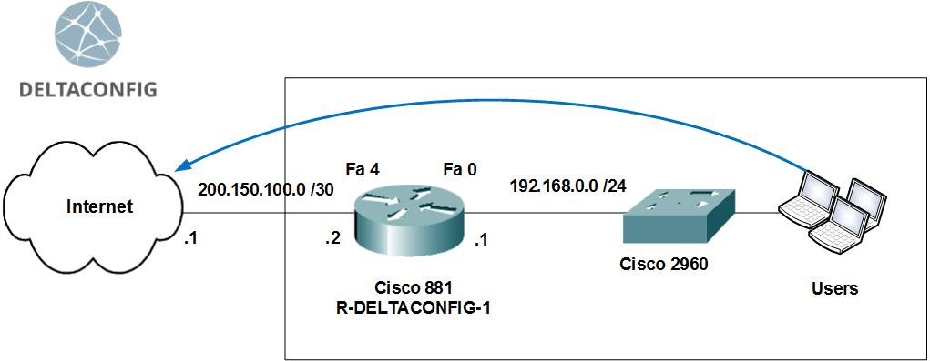
Let’s see how to connect an office to the Internet using a Cisco router.
Let’s take Cisco 881 for example. Commands for configuration of other routers (1841, 2800, 3825…) will be the same. They may differ only in configuration of interfaces, i.e. their names and numbers.
The scheme includes
an Internet connection with a static address
several PCs in the office local network
a router
a switch for creating an office local network
Task: provide access for LAN computers to the Internet
Step 0. Clearing the configuration
The first thing to do when configuring a new router is to completely clear the startup configuration.
(Do it only on new or test devices!)
To do that, connect via a special console cable to the router console port, enter the command line and do the following:
Enter the privileged mode(#), you may need to enter a login name/password for that.
Erase the startup configuration
Reload the router
The router will reboot within 3 minutes and initial configuration dialog will appear. Type "no" and move to next step.
--- System Configuration Dialog ---
At any point you may enter a question mark '?' for help.
Use ctrl-c to abort configuration dialog at any prompt.
Default settings are in square brackets '[]'.
Would you like to enter the initial configuration dialog? [yes/no]:
The current router configuration will have only default technological lines, and you can start the main configuration.
Step 1. Device name
Use the hostname «device name» command to set a router name. It will help you in future.
Step 2. Configuration of interfaces
We should configure two interfaces: external and internal ones.
The external interface will be used for connecting to the Internet. It will have the IP address and network mask provided by the ISP.
The internal interface will be configured for the local network 192.168.0.0 /24
For example, the ISP has provided us with the following addresses:
Network 200.150.100.0
Subnet mask 255.255.255.252 or /30
Default gateway 200.150.100.1
Let’s configure the external interface: set an IP address and a network mask and enable it using the no shut command
Then, connect this router interface to the port of the provider’s equipment using a direct patch cord and check its availability with the ping command.
At first, the own interface
Then, the adjacent address – a provider’s gateway
After making sure that the provider’s gateway is available, we should configure the internal interface.
The local network will have the following addresses:
Network 192.168.0.0
Subnet mask 255.255.255.0
Internal router address acting as an Internet gateway for all network hosts, 192.168.0.1
I recommend starting the range of internal network addresses (users, printers, servers, etc.) with 192.168.0.5
The max available address in this network is 192.168.0.254
Let’s reserve addresses from 192.168.0.2 to 192.168.0.4 for emergency technological needs
To configure the internal interface of the local network, enter the Vlan 1 configuration mode, set an IP address and link it with one of the router’s physical interfaces (Fa 0).
Choose a physical router interface and link it with the virtual Vlan.
This could help for better understanding:
=> interface => interface
The IP address is assigned to the Vlan X virtual interface, which is linked with the Fastethernet Y physical interface.
Connect the Fa 0 router interface to the switch with the working stations of the local network or directly with the administrator’s working station.
Then, check the availability of this router interface using the ping command from the command line.
Step 3. Configuration of the remote router access
You can access the router console not only using a console cable, but also remotely using the Telnet (data is transferred unsecure) and SSH (secure connection).
Let’s see how to configure the secure connection.
Enable the SSH version 2 protocol and set any domain name.
Generate the rsa keys required for connection. Enter 1024 at the request.
Set a user name with administrator rights and the password (*****)
Enable authorization through the device local base (the user you have created a line before).
Set a password for the privileged mode.
Then, using a special program supporting the SSH protocol, you can remotely enter the router console from any working station of the local network. For authorization, enter the login name and password set earlier.
You can learn more about access to the device using the SSH protocol in this article.
Step 4. Default gateway
For routing of packages to the Internet, we should define a default gateway of the device.
After that, you can check not only availability of provider’s equipment, but of the whole Internet connection.
For that, launch ping to any address in the external network in digital format (I recommend configuring DNS for the local network after configuration of the router).
Let’s take the google's address (8.8.8.8) for example.
Important!
Please, note that currently ping of external addresses works only (!) when launched from the management console by the router. Working stations of the local network do not have Internet access.
Step 5. Configuration of network address translation (NAT)
For Internet access from the local network, we should dynamically translate all internal addresses to a certain external IP address.
In our case, as the ISP gives us only with one external address 200.150.100.2 (defined by the /30 subnet mask as given in the example above), all local network addresses should be translated to it.
Define a list of internal addresses for translation to the external address.
Define the internal interface for translation.
Define the external interface for translation.
Create the network address translation (NAT) rule.
As a result, you should have Internet access from any workstation of the local network if their default gateway is the internal IP address of the router (192.168.0.1).
You can check this using the ping command to an Internet address from the command line. The address should be better in digital format to avoid potential problems with DNS names (Use 8.8.8.8 to check the connection).
Important!
Do not allow full Internet access from all local network addresses. After checking the connection, I recommend limiting the Internet access only to certain addresses – for example, a proxy server and working stations of the administrator/director.
You can learn more about how to do it in the article “a little about access lists”.
Important!
Don’t forget to save the changes you made to the configuration with the write or copy run start commands. Otherwise you will lose all changes after the next reload.
This article was written by Alexey Yurchenko
Back to Table of contents